What differs between VIC6040F and VIC9060F?
VIC6040F lists a 600*400mm working area, while VIC9060F lists 900*600mm. Their published power range is shared at 80-600W.

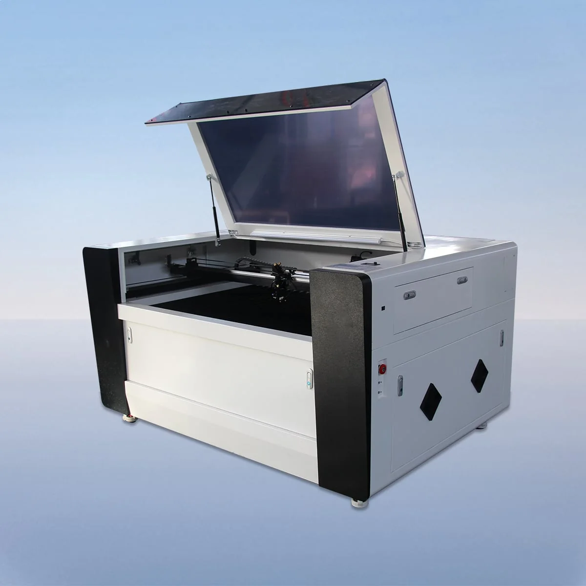
Laser Cutting Machine
VIC-F is a CO2 laser cutting machine series with a fully enclosed cutting area. The structure described for it includes a CO2 head and tube, linear guides, a stepper motor and belt drive. An aluminum blade worktable is also described for the configuration.
There are seven working-area choices and a shared 80-600W power range. For a purchase, identify the workpiece format first, then describe the power and table configuration being considered. The enclosed structure is one part of the machine description, rather than a substitute for those selections.
Choose an individual model below to view its complete technical specification. The series overview shows selected parameters for comparison.
VIC6040F has a 600*400mm working area and VIC9060F has 900*600mm. VIC1390F offers 1300*900mm, followed by VIC1610F at 1600*1000mm. Use the full outline and orientation of the intended work when comparing these formats.
VIC1318F and VIC1325F share a 1300mm first dimension, with 1800mm and 2500mm as their second dimensions. VIC1530F provides 1500*3000mm. These are processing-area entries. The external dimensions of the selected enclosed machine are separate information to obtain for the installation.
The listed worktable alternatives are Knife Table or Honeycomb Table. The description of aluminum blades does not mean both table types come together. Identify the chosen surface so that the configuration matches the proposed workpiece arrangement.
VIC-F CO2 laser cutting machine planning should show how the work reaches the cutting area. Describe the incoming stock, its dimensions and the intended loading method. Then show how completed parts will be removed. These details give the enclosed-machine discussion a concrete handling requirement.
The part drawing serves a different role from the handling layout. It identifies the material, thickness, contours and any other requested operations. Keep the finished dimensions and required result on that drawing, with a visible revision reference so that later changes remain identifiable.
For mixed work, provide representative designs and indicate which recur most often. A single largest outline may be relevant to area selection, but it does not explain the rest of the workload. Label quantities as your proposed work rather than as a production result already established for the machine.
Ruida control and USB interface are listed. The graphic-format examples are PLT, DXF, BMP, JPG and AI. Submit a file in the format you intend to use and explain any separate layers or operations in the accompanying notes.
The specification lists 150mm/s cutting speed. Minimum line width is no greater than 0.15mm, position accuracy is 0.01mm and repetition accuracy is 0.02mm. Keep their distinct meanings when placing machine specifications beside the part requirements; the table is not a material-by-thickness results chart.
The electrical entries are 220V/50HZ and 110V/60HZ. Specify the required supply together with the model, power and worktable. Put the equipment position and stock routes on a workshop layout, then obtain the actual outside dimensions and access details to complete it.
The source confirms the fully enclosed cutting-area structure. No safety rating or certification is established by that description. Identify the actual supplied-system details needed for the proposed workspace instead of treating the word enclosed as a complete installation specification.
VIC6040F lists a 600*400mm working area, while VIC9060F lists 900*600mm. Their published power range is shared at 80-600W.
The cutting area is described as fully enclosed. This confirms a structural feature without establishing a particular certification or safety rating.
Their working areas are 1300*1800mm and 1300*2500mm. The second dimension distinguishes these two formats despite the common 1300mm first dimension.
Knife Table or Honeycomb Table are listed alternatives. Have the chosen surface identified alongside the requested model and power.
Show stock dimensions, the proposed loading method and removal of completed pieces. Add the machine position to a layout and obtain actual equipment access details for that plan.
Share your material, dimensions and process. Start a conversation about the right configuration.