What laser values identify VIM100CF?
The published values are 100W power and 10.6 μm wavelength. The model belongs to the VIM-CF flying CO2 family, whose design is described for marking moving products or material.

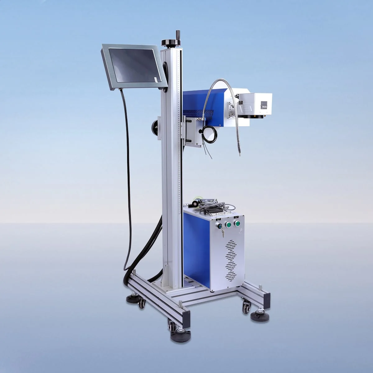
Laser Marking Machine
VIM100CF is a 100W flying CO2 laser marking model with a published wavelength of 10.6 μm. Its VIM-CF configuration is designed for marking moving materials or workpieces. Within the family, the lower adjacent power is 60W on VIM60CF and the upper adjacent entry is 150W on VIM150CF.
The selected power belongs in a wider equipment schedule. The series description includes the CO2 tube, air cooling, galvo scanner, field lens and red dot positioning. Their arrangement at the marking point needs to be considered with the product's motion and the graphic it is intended to carry.
| Specification | VIM100CF |
|---|---|
| Laser Power | 100W |
| Laser Wavelength | 10.6 μm |
Configuration options vary by model. Confirm the final specification, selected components and operating requirements with your quotation.
The 100W value identifies the laser model, not a complete production-line capacity. Keep the required mark dimensions, substrate and placement visible when discussing the power choice. If several power models are being compared, use the same task information so the proposals address the same work rather than different assumptions.
The red dot pointer provides a visible alignment reference, while the field lens and galvo scanner are separately listed components. Ask the proposal to identify the optical configuration and marking field. The graphic's dimensions and location should accompany that request, since a model number does not establish the field area.
The controls provide parameter setting, adjustment and real-time monitoring. Explain whether your line repeats one graphic or runs several jobs with different content. Review those requirements with the offered interface, keeping any requested data or automation connection explicit rather than assuming it is part of the standard equipment.
Wood, acrylic and glass appear in the CO2 tube configuration's marking and engraving scope. Identify the actual substrate and finish for the VIM100CF application. Describe the appearance required from the mark and any inspection needs, without treating the material list as a test record for every product or surface treatment.
A useful layout shows the product before, at and after the proposed marking point. Include movement direction, item spacing, the surface presented and the access available for equipment and operators. These are planning inputs; the flying arrangement does not establish a supplied conveyor, a guaranteed line speed or an unattended production system.
No numerical field, minimum character dimension or software brand is assigned here. Establish those configuration details for the offered VIM100CF equipment, with the 100W model and intended artwork kept together in the schedule. Do not substitute specifications from a desktop marker simply because it also uses a CO2 source.
The equipment description includes air cooling and an interlock that stops operation when a safety door or panel opens. Review the operating instructions and protective arrangement for the actual installation. Neither feature supplies a continuous-duty promise or a certification for the line surrounding the marker.
For a clear commercial scope, list the marker configuration separately from requested supports, handling equipment or other accessories. Identify fixed constraints in the existing line and keep drawing revisions consistent. The enquiry can then define a particular 100W marking task and proposed installation instead of leaving the equipment boundary implicit.
The published values are 100W power and 10.6 μm wavelength. The model belongs to the VIM-CF flying CO2 family, whose design is described for marking moving products or material.
VIM60CF is listed at 60W and VIM150CF at 150W. Compare them with VIM100CF using the same substrate, artwork and movement requirements rather than assuming results from power alone.
No. Power and marking field are separate configuration items, and no field value is assigned here. Request the optics and field proposed for the actual graphic.
Provide the orientation, movement direction, spacing and desired mark position, with artwork dimensions and material details. Include a layout showing available access around the proposed marking point.
The description establishes a moving-workpiece marking arrangement. It does not establish a conveyor or complete handling line in the supplied package, so those items need a separate scope statement.
Share your material, dimensions and process. Start a conversation about the right configuration.