What is the VIC1530E working area?
The table lists 1500*3000mm. Compare both dimensions with the intended layout rather than treating the model number as a complete size description.

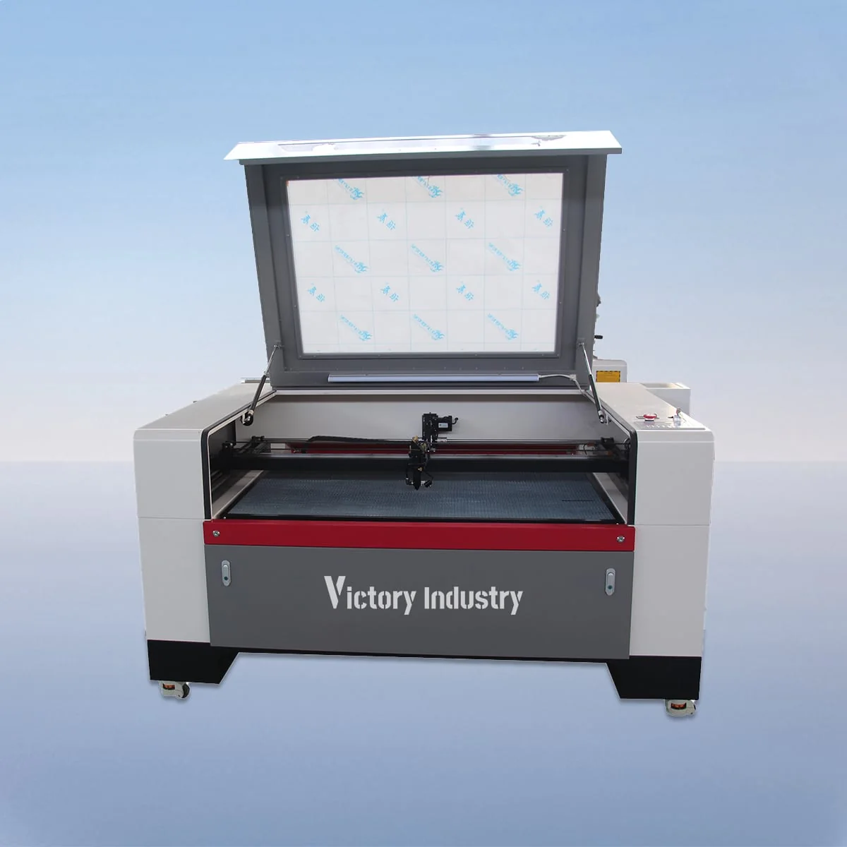
Laser Cutting Machine
VIC1530E has a published working area of 1500*3000mm in the VIC-E CO2 laser cutting series. Its family description includes an electric lifting table for adjusting workpiece height. The structure also lists a CO2 head and tube, linear guides, stepper motors and belt drive, with an 80-600W laser power range.
A useful installation brief keeps three dimensions of the workpiece separate from the external equipment outline. The working area describes the rectangle available for comparison with the layout, while the height and support arrangement require their own review. Request the installation information for the chosen configuration before treating the area entry as a site plan.
| Specification | VIC1530E |
|---|---|
| Working Area | 1500*3000mm |
| Laser Type | CO2 Laser |
| Working Table | Knife Table or Honeycomb Table |
| Laser Power | 80-600W |
| Power Supply | 220V/50HZ, 110V/60HZ |
| Min Line Width | ≤0.15mm |
| Position Accuracy | 0.01mm |
| Repetition Accuracy | 0.02mm |
| Cutting Speed | 150mm/s |
| Control System | Ruida (USB Interface) |
| Graphic Format Support | PLT, DXF, BMP, JPG, AI, etc |
Configuration options vary by model. Confirm the final specification, selected components and operating requirements with your quotation.
The VIC1530E working area measures 1500mm by 3000mm, compared with 1300*2500mm for VIC1325E. Retain both dimensions when comparing layouts. Another family option, VIC1610E, lists 1600*1000mm, so model selection cannot be reduced to assuming that VIC1530E exceeds every other model in each direction.
The electric lifting table adjusts workpiece height. The admitted description does not state its stroke or load capacity. Provide the object dimensions and any proposed support, and request the adjustment details for that arrangement. Height adjustment alone does not establish automatic focusing, arbitrary thickness accommodation or a particular handling method.
Knife or honeycomb tables are published alternatives, and a red dot pointer is optional for visible material positioning. Confirm the intended work surface and positioning equipment in the offer. If installation planning depends on how the object reaches the table, describe that requirement and request the proposed arrangement explicitly.
The source describes cutting and engraving and names acrylic, wood and plastics as examples. Specify the actual material grade and thickness, along with the required cut or engraved appearance. The working-area dimensions and material names do not provide a tested processing result or an approved thickness for your job.
Imagine a site plan being prepared before equipment selection is finalized. Send the proposed location sketch, the workpiece drawing and the intended artwork as separate references. Ask for external dimensions and access information for the quoted configuration. Keep the object-height discussion linked to that configuration instead of inferring it from the plan view.
Ruida control with a USB interface is listed, and supported graphic formats include PLT, DXF, BMP, JPG and AI. Identify the scale and units of each drawing. Where a site plan, workpiece drawing and artwork are supplied together, use clear references so their different purposes and dimensional scales remain distinguishable.
The table gives 220V/50HZ and 110V/60HZ supply entries. State the supply available at the destination and request the corresponding version, selected laser power and agreed table equipment. The 80-600W range does not define a particular delivered rating until the proposal identifies the selection.
Position Accuracy of 0.01mm, Repetition Accuracy of 0.02mm and Cutting Speed of 150mm/s are listed independently. Provide the required component dimensions and visual result separately. Any production target should refer to the actual material, drawing revision and proposed setup, while installation questions should refer to the external equipment arrangement.
The table lists 1500*3000mm. Compare both dimensions with the intended layout rather than treating the model number as a complete size description.
No. Request external equipment dimensions and access information separately. The published field describes working area, not the complete installed arrangement.
Ask about stroke and load capacity for the proposed object and support. The source establishes workpiece-height adjustment but does not give numerical limits for those fields.
Knife or honeycomb surfaces are listed, with an optional red dot pointer. Confirm the selected table and any requested pointer in the equipment schedule.
Supply a site sketch, available electrical supply, dimensioned workpiece drawing and artwork references. Keep scales, revisions and the proposed support arrangement clearly identified.
Share your material, dimensions and process. Start a conversation about the right configuration.