What is the VIC1390C working area?
1300*900mm. Check the full material and layout dimensions against both directions, and obtain the external machine dimensions separately.

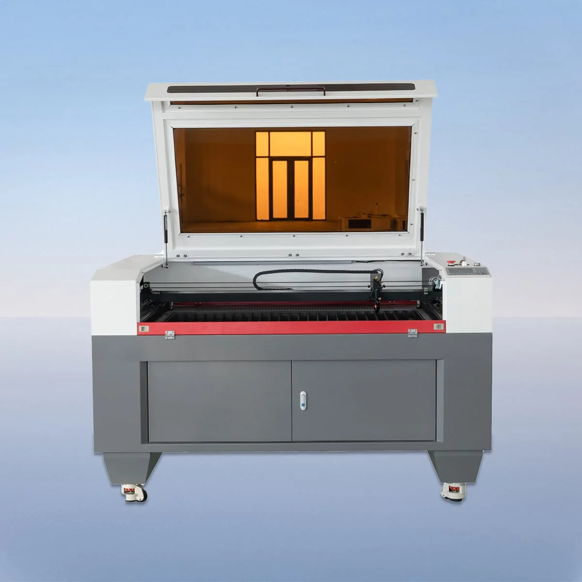
Laser Cutting Machine
VIC1390C is a VIC-C CO2 laser cutting model with a 1300*900mm working area. The series includes a CCD camera for cutting-process monitoring, material alignment and positioning. Its published component arrangement uses a CO2 head and tube, linear guides, stepper motors and a belt drive system.
Use the 1300*900mm rectangle to organize the complete production drawing. If an enquiry includes an individual part, a multi-part layout and an illustration of the desired result, label each file clearly. Those documents answer different questions, and the camera discussion should refer to the same version of the intended work.
| Specification | VIC1390C |
|---|---|
| Working Area | 1300*900mm |
| Laser Type | CO2 Laser |
| Working Table | Knife Table or Honeycomb Table |
| Laser Power | 80-600W |
| Power Supply | 220V/50HZ, 110V/60HZ |
| Min Line Width | ≤0.15mm |
| Position Accuracy | 0.01mm |
| Repetition Accuracy | 0.02mm |
| Cutting Speed | 150mm/s |
| Control System | Ruida (USB Interface) |
| Graphic Format Support | PLT, DXF, BMP, JPG, AI, etc |
Configuration options vary by model. Confirm the final specification, selected components and operating requirements with your quotation.
The VIC1390C working area is larger in both listed dimensions than VIC9060C at 900*600mm. It is a different rectangle from VIC1610C at 1600*1000mm. Compare the actual blank and layout with those values; the model names do not establish an automatic nesting result or the number of saleable pieces from your material.
CCD monitoring and alignment should be discussed alongside the physical references on the work. Show the edge, outline or other feature you intend to use when positioning the material. The published camera description does not provide an automatic defect-detection rate, a correction algorithm or a separate print-registration accuracy figure.
The specification offers knife or honeycomb working tables, and the configuration section describes an aluminum blade table. Have the selected surface recorded with the model. If the task needs a particular support or positioning accessory, describe that requirement so its inclusion can be resolved in the equipment offer.
The source positions VIC-C for CO2 cutting and engraving and names wood and acrylic. Your application brief should go further: specify the material, thickness, required outline and appearance of any engraved area. Keep acceptance requirements distinguishable from a reference photograph, which may not describe the same material or process.
Imagine that a layout changes after the first quotation discussion. Send the new revision with the altered outlines identified, even if the outer blank dimensions stay the same. Ask whether the proposed positioning approach and selected configuration still address the changed task. Retain the earlier response with its original drawing rather than applying it silently to the revision.
Ruida control with a USB interface is listed, together with PLT, DXF, BMP, JPG and AI among the supported formats. Specify the intended scale and units when sending artwork. For a layout containing both cutting and engraving requirements, explain which result each part of the supplied information is intended to define.
The published laser power range is 80-600W. Ask the proposal to identify the selected power instead of leaving that range as the final equipment description. The two electrical entries, 220V/50HZ and 110V/60HZ, likewise require a specified version appropriate to the destination; they do not establish automatic switching between supplies.
Keep the listed Min Line Width of ≤0.15mm separate from your finished-feature requirement. Position Accuracy is 0.01mm, Repetition Accuracy is 0.02mm and Cutting Speed is 150mm/s. Those fields are not a test report for the revised layout. Agree how the required result would be checked for the configuration under discussion.
1300*900mm. Check the full material and layout dimensions against both directions, and obtain the external machine dimensions separately.
The VIC-C series describes a CCD camera for process monitoring, material alignment and positioning. Automatic inspection or correction performance is not specified here.
Identify the revision and ask which configuration or application conclusions remain applicable. A changed outline may need a new discussion even when the blank size is unchanged.
Knife or honeycomb. Aluminum blades are described for the knife arrangement; ask the offer to state its selected table and any requested accessories.
No result for your particular part is established by that field. Keep the required feature dimensions and assessment criteria in the application brief.
Share your material, dimensions and process. Start a conversation about the right configuration.