What area does VIC1318C provide?
The published working area is 1300*1800mm. Include the full blank and layout dimensions when discussing whether this rectangle addresses your requirement.

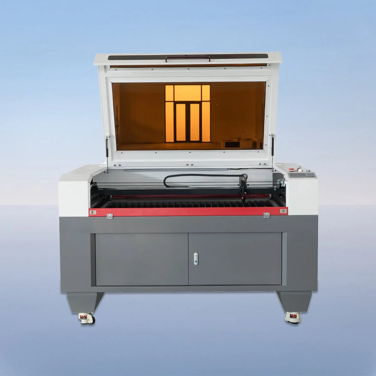
Laser Cutting Machine
VIC1318C lists a 1300*1800mm working area in the VIC-C CO2 laser cutting family. A CCD camera is described for monitoring the process and assisting material alignment and positioning. The machine series uses a CO2 cutting head and tube with linear guides, stepper motors and belt drive.
For a longer layout, compare this model with VIC1325C at 1300*2500mm. They share the first listed working-area dimension while the second changes. Keep the blank orientation, positioning references and full layout with that comparison so the choice answers a real requirement rather than a preference for a larger number.
| Specification | VIC1318C |
|---|---|
| Working Area | 1300*1800mm |
| Laser Type | CO2 Laser |
| Working Table | Knife Table or Honeycomb Table |
| Laser Power | 80-600W |
| Power Supply | 220V/50HZ, 110V/60HZ |
| Min Line Width | ≤0.15mm |
| Position Accuracy | 0.01mm |
| Repetition Accuracy | 0.02mm |
| Cutting Speed | 150mm/s |
| Control System | Ruida (USB Interface) |
| Graphic Format Support | PLT, DXF, BMP, JPG, AI, etc |
Configuration options vary by model. Confirm the final specification, selected components and operating requirements with your quotation.
The VIC1318C working area is a two-dimensional specification. It does not state an automatic feed length or describe how oversize material can be processed. If a blank extends beyond the intended layout, include its complete dimensions and ask how it would be presented. Do not substitute the finished-part size for the incoming material outline.
The CCD camera's published role is monitoring, alignment and positioning. Identify what should be aligned and which features define the intended location. For a long layout, show the relationship between those references and the complete cutting pattern. No automatic correction or print-registration accuracy is established by the camera description on this page.
Knife or honeycomb is the table choice in the specification. The series configuration describes an aluminum blade worktable. Ask the offered setup to name its chosen surface and any proposed material supports. Those details should remain associated with the workpiece being discussed, rather than assumed identical for every possible layout.
The original VIC-C description covers CO2 cutting and engraving, naming wood and acrylic. State the actual material, thickness and operation for your intended work. If different materials use similar outlines, list them separately so a discussion about one material cannot be mistaken for a confirmed result on the others.
Imagine a long blank containing several related components. Send the full arrangement with the individual drawings, indicating which edge or other feature will guide positioning. Describe any required relationship between the components after cutting. The camera discussion can then address that setup without assuming a particular output quantity, handling method or finished dimensional result.
Ruida control through a USB interface is listed, with PLT, DXF, BMP, JPG and AI among the supported graphic formats. Keep the file dimensions, units and revision clear. If an illustration shows how the blank is positioned, distinguish it from the cutting artwork and label the intended reference direction.
The laser power field spans 80-600W. Have the selected power named for the VIC1318C offer, together with its electrical version. The published supply entries are 220V/50HZ and 110V/60HZ. Confirm the version against the installation supply rather than treating both entries as automatic compatibility in a single delivered machine.
Cutting Speed is listed at 150mm/s; Position Accuracy and Repetition Accuracy are 0.01mm and 0.02mm. Keep these catalogue entries distinct from the result required across your layout. Ask how the proposed task would be assessed, and request machine dimensions and access requirements before finalizing the position of the equipment in the workshop.
The published working area is 1300*1800mm. Include the full blank and layout dimensions when discussing whether this rectangle addresses your requirement.
VIC1325C lists 1300*2500mm. Its first listed dimension matches VIC1318C, while the second is longer; compare the complete proposed layout.
No automatic feeding function is assigned to VIC1318C here. Describe your required material presentation separately when requesting a configuration.
It describes monitoring, material alignment and positioning. It does not establish automatic defect detection or a guaranteed result across the full layout.
Provide its complete outline, material and thickness, the component arrangement and positioning references. State the finished requirements and identify the relevant artwork revision.
Share your material, dimensions and process. Start a conversation about the right configuration.