How do VIW1500S and VIW2000S differ?
The listed powers are 1500W and 2000W respectively. VIW3000S provides a 3000W option, while all three share the published 1080nm wavelength and water-cooling method.

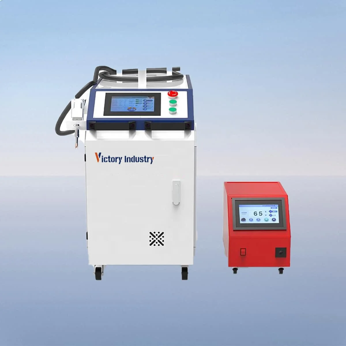
Laser Welding Machine
VIW-S is a handheld laser welding machine series with an automatic wire-feeding device. The source describes filler wire being fed into the weld pool, alongside a handheld welding head, laser generator and industrial water chiller. The machine structure includes wheels, allowing its position to be considered as part of the workshop layout.
The three published models are VIW1500S at 1500W, VIW2000S at 2000W and VIW3000S at 3000W. All list a 1080nm wavelength and water cooling. The wire-feeding arrangement is a distinct configuration feature to discuss with the joint information, rather than treating the power rating as the complete welding specification.
Choose an individual model below to view its complete technical specification. The series overview shows selected parameters for comparison.
The automatic wire-feeding device supplies filler wire to the weld pool. Its presence establishes the feeding function, but no wire diameter or feed-speed range is assigned here. If your process requires a particular wire, identify it in the enquiry and request the corresponding feeder and head configuration for the proposed job.
The controls support settings and real-time monitoring. The source describes adjustment of power, speed and focus, and its Features section also lists wire-feed settings. A useful demonstration should connect these controls to the intended joint and operating sequence rather than show unrelated settings without the workpiece context.
Raycus, JPT, IPG and Max are the named laser source options. The configuration also includes an emergency stop button and a casing for the internal components. The casing is part of the machine structure, while the complete welding workstation needs its own operating and protective arrangement. Obtain that information for the equipment actually proposed.
A welding request should describe the material, thickness, joint geometry and seam path. Where filler wire is part of the intended process, include the required wire information and any existing process requirements. These details give the automatic feeding feature a specific task to address without assuming a stronger joint or a guaranteed result from the presence of a feeder.
Show how the workpiece is supported and where the operator approaches the seam. Identify whether the part can be repositioned and what nearby features restrict access. Keep the required finished result and inspection criteria with the drawing. No material-thickness or welding-gap capacity is assigned on this page, so selection needs those actual job requirements.
The listed fiber length is standard 10m, with maximum support of 20m. In the layout, show the machine position, workpiece position and proposed route between them. Confirm the actual supplied fiber length instead of treating the maximum supported entry as the standard package or as an unrestricted reach around the work area.
English, Chinese, Japanese, Korean and Russian are the published interface languages. State the language required by the operating team. Working humidity is below 70% with no condensation, which belongs in the installation review alongside the water chiller and the selected equipment's connection requirements.
Keep model, source, fiber length, head and wire-feeding configuration together in the equipment schedule. Attach the joint drawing and identify any requested support or handling accessories separately. This allows proposals to be compared around the same welding task, with the feeding function clearly included in the scope rather than left as an assumed extra.
The listed powers are 1500W and 2000W respectively. VIW3000S provides a 3000W option, while all three share the published 1080nm wavelength and water-cooling method.
The source describes automatic feeding of filler wire into the weld pool. It does not specify a wire diameter or feeding-speed range here, so confirm those details for the intended process.
The source lists power, speed and focus adjustment, plus wire-feed settings, with real-time monitoring. Review the offered controls using the proposed joint and required operating sequence.
The published standard is 10m, with maximum support of 20m. Identify the length supplied with the proposed machine and review the route to the workpiece in the layout.
Provide material, thickness, joint drawing, seam path and any required filler-wire information. Add the part support arrangement, required finished result and requested source or power model.
Share your material, dimensions and process. Start a conversation about the right configuration.